Explains the concentration limits for successful zeta potential measurements to be made. A case study is used to illustrate the limits of concentration and describes what happens to the quality of data if the sample concentration is inappropriate.
The Zetasizer Nano series can measure particle size, zeta potential and molecular weight. The incorporation of NIBS® technology enables sizing measurements to be performed on concentrated, turbid samples. However, the concentration requirements for measuring the zeta potential of samples is much lower than that for sizing measurements. This technical note aims to explain the concentration limits for successful zeta potential measurements to be made. A case study is used to illustrate the limits of concentration and describes what happens to the quality of data if the sample concentration used is inappropriate.
The optical configuration on the Zetasizer Nano for zeta potential measurements is shown in figure 1. Firstly, a laser (1) is used as a light source to illuminate the particles within the sample. For zeta potential measurements, this light source is split to provide an incident and reference beam. The intensity of the reference beam is factory set and is normally between 2500 and 3500kcps. The incident laser beam passes through the center of the sample cell (2), and the scattered light is detected at a forward angle (3). When an electric field is applied across the cell, any particles moving through the measurement volume will cause the intensity of light detected to fluctuate with a frequency dependent on the particle speed and this information is passed to a digital signal processor (4) and PC (5). The Zetasizer Nano software analyses the detected data to obtain the electrophoretic mobility and hence zeta potential information.
Figure 1: Optical configuration of the Zetasizer for zeta potential measurement
This optical configuration is known as heterodyne detection. In this mode of operation, the scattered light from the sample is mixed with unscattered laser light (the reference beam). The ratio of the intensity of the reference beam to scattered light is carefully controlled using an attenuator (6) and is set to around 10:1 in the Nano series. This attenuator varies the intensity of the laser and hence varies the intensity of the scattering. For samples that do not scatter much light, such as very small particles or samples of low concentration, the amount of scattered light being detected must be increased. The attenuator will therefore automatically allow more light through to the sample. For samples that significantly scatter light, such as large particles or samples at high concentration, the attenuator automatically reduces the amount of light that passes through to the sample.
To correct for any differences in the cell wall thickness and dispersant refraction, compensation optics (7) are installed to maintain optimum alignment.
When a zeta potential measurement is started in the Zetasizer Nano, the intensity of the reference beam is measured and displayed in the Log Sheet. The intensity of the incident beam is adjusted using the attenuator so that the intensity of the scattered light being detected is no greater than 1/10th that of the reference beam. For example, if the reference beam intensity is measured as being 2600kcps, then the attenuator will adjust until the intensity of the scattered light being detected is no more than 260kcps. The attenuator in the Zetasizer Nano has 11 positions covering an attenuator range of 100% to 0.0003%. The relationship between the attenuator position and the transmission value is shown in table 1. The transmission value is the percentage of laser light that enters the sample cuvette.
Table 1: Relationship between the attenuator index and transmission value
Attenuator Index | Transmission |
1 | 0.0003 |
2 | 0.003 |
3 | 0.01 |
4 | 0.03 |
5 | 0.1 |
6 | 0.3 |
7 | 1 |
8 | 3 |
9 | 10 |
10 | 30 |
11 | 100 |
The minimum count rate that is acceptable for a zeta potential measurement to proceed is set to 20kcps. If the count rate detected is less than this value, the measurement will abort.
It has been seen from the previous discussion that the laser beam has to penetrate the sample for scattered light at a forward angle to be detected. Therefore, in general, samples for zeta potential measurements have to be optically clear. The minimum and maximum sample concentrations that can be measured will depend on the following factors:
The minimum count rate of scattered light required to make a measurement is 20kcps. Therefore, the minimum concentration required will depend upon the relative refractive index (the difference in refractive index properties of the particle and the medium) and the particle size. The larger the particle size, the more scattered light it produces and hence the lower the concentration that can be measured. For example, consider a dispersion of a ceramic powder such as titania which has a particle refractive index of around 2.5. This relative refractive index results in a very high level of scattering. Therefore, the minimum concentration of titania with a mean particle size of around 300nm that can be measured could be as low as 10-6% w/v.
If the relative refractive index becomes lower, such as with proteins for example, the minimum concentration will be much higher. A minimum concentration of between 0.1 and 1% w/v may be required to obtain sufficient scattering from a protein solution in order to make a successful zeta potential measurement.
Ultimately, the minimum concentration required for successful zeta potential measurements of a particular sample has to be determined experimentally.
There is not a simple answer to the question what is the maximum concentration that can be measured during a zeta potential measurement in the Zetasizer Nano. The factors discussed above all have to be taken into account i.e. the particle size and polydispersity and the optical properties of the sample.
The scattered light from a sample in a zeta potential measurement is detected at a forward angle in the Zetasizer Nano. Therefore, the laser beam has to penetrate through the sample. If the concentration of the sample becomes too high, then the laser beam will become attenuated by the particles reducing the scattered light that is being detected. To try and compensate for these effects, the attenuator position in the instrument will be adjusted to a higher index i.e. a higher transmission.
Results are now presented of a case study to try and illustrate the concentration limits for successful zeta potential measurements. Figure 2 shows the results obtained from a series of zeta potential measurements on a sample of Intralipid. This is a commercial oil in water emulsion sample with a mean size of around 220nm. The intensity size distribution from a dynamic light scattering measurement obtained at 0.01% w/v concentration is shown in figure 3. All zeta potential measurements were made in the disposable zeta cell (DTS1070) using the General Purpose protocol at 25°C. A manual duration of 40 sub runs was used.
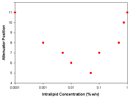
Figure 2: A plot of the attenuator position automatically selected by the Zetasizer Nano at various Intralipid concentrations diluted in DI water
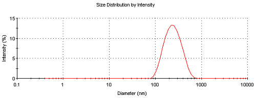
Figure 3: Intensity size distribution of Intralipid measured at a concentration of 0.01% w/v
At low concentrations (0.0001% w/v), the sample scatters low levels of light and therefore the attenuator adjusts to position 11 (100% transmission). As the concentration increases, more scattering is detected and so to ensure that the ratio of scattered light to reference beam intensity is appropriate, a lower attenuator position is selected (lower transmission). This effect continues up to a concentration of 0.05% w/v at which an attenuator position 5 is used for the measurements (0.1% transmission).
At concentrations greater than 0.05%, the laser beam becomes attenuated by the large numbers of particles in its path and so the attenuator position selected now begins to increase to ensure enough scattering is being detected. This effect continues up to a concentration of 1%. At this concentration, the attenuator index selected was 11 (i.e. 100% transmission). This is due to the large attenuation of the laser beam by the high concentration of particles resulting in low levels of scattered light being detected.
Figure 4 is a photograph of the Intralipid sample concentrations measured for figure 2. It is hoped that this gives the reader an appreciation of the turbidity at which a sample can be successfully measured in a Nano instrument. The concentrations of the Intralipid samples in the various cuvettes are shown in table 2.
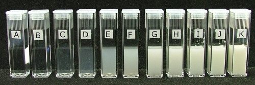
Figure 4: Photograph showing the various concentrations of Intralipid that were used in figure 2. The concentrations of the Intralipid samples were A = 0.0001% w/v, B = 0.001% w/v, C = 0.005% w/v, D = 0.01% w/v, E = 0.05% w/v, F = 0.1% w/v, G = 0.5% w/v, H = 0.75% w/v, I = 1% w/v, J = 2% w/v and K = 10% w/v (neat sample). The zeta potentials of samples A to I were successfully measured in the Nano i.e. up to 1% w/v concentration.
Table 2: The Intralipid concentrations of the samples contained in the various cuvettes shown in figure 4
Cuvette Label | Intralipid Concentration (% w/v) |
A | 0.0001 |
B | 0.001 |
C | 0.005 |
D | 0.01 |
E | 0.05 |
F | 0.1 |
G | 0.5 |
H | 0.75 |
I | 1 |
J | 2 |
K | 10 |
The next section discusses what inappropriate sample concentrations have on the quality of the data obtained from the measurements.
The mean zeta potentials of samples A to I were successfully measured in the Nano i.e. up to 1% w/v concentration. The mean zeta potential is determined from phase analysis light scattering and further information on this technique can be obtained from the Malvern Instruments website.
Figure 5 shows the phase plot obtained from measurements of sample I (1% w/v) where as figure 6 is the phase plot from sample J (2% w/v). The attenuator indices automatically chosen for both these samples were 11 (100% transmission) indicating very low intensities of scattered light detected. However, whereas the phase plot obtained with sample I is excellent, the data obtained for sample J is very poor. The comparison in data quality is seen very clearly when the phase plots from both samples are over plotted (figure 7). The upper limit of concentration for reliable mean zeta potential values for this sample is therefore 1% w/v.
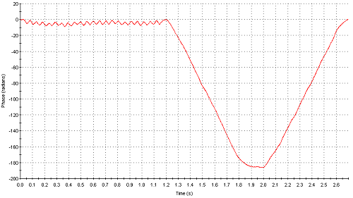
Figure 5: Phase plot obtained from measurement of sample I (1% w/v)
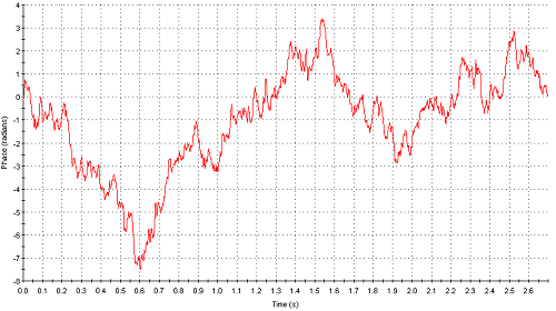
Figure 6: Phase plot obtained from measurement of sample J (2% w/v)
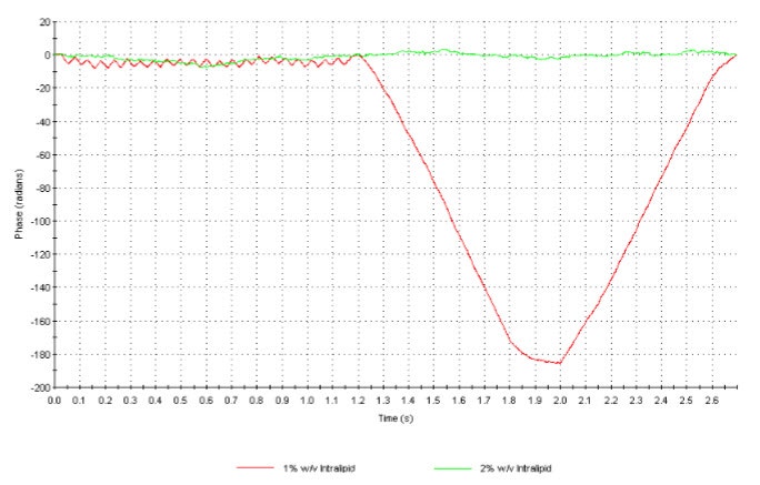
Figure 7: Overplot of the phase plots obtained for samples I (1% w/v) and J (2% w/v) illustrating the difference in data quality
The zeta potential distribution is obtained from the frequency distribution that result from a Fourier transform during the slow field reversal (SFR) part of the measurement. Even though the mean zeta potential can be measured at concentrations of up to 1% w/v, the zeta potential distributions obtained at this concentration are very broad due to the low signal to noise ratio of the detected light. Figure 8 is an over plot of the frequency distributions obtained for samples I (1% w/v) and G (0.5% w/v) respectively. The distribution for sample I is very broad with the zeta potential deviation around 80mV. This is the standard deviation of the peak and is indicative of the poor signal to noise ratio obtained from this measurement. The frequency distribution obtained for sample G (0.5% w/v) has a zeta potential deviation of around 10mV due to the much narrower distribution width. Therefore, the upper limit of concentration in order to obtain good zeta potential distributions is 0.5% w/v.
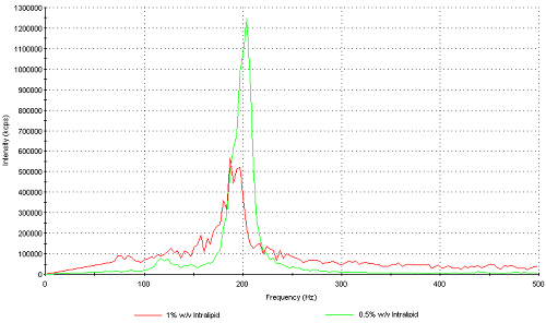
Figure 8: Frequency distribution plots obtained from samples I (1% w/v) and G (0.5% w/v) respectively.
The lower and upper limits of concentration for the zeta potential of a sample to be successfully measured are not easy to define. This is because several factors will dictate these concentration limits and these have been discussed in this technical note.
Ultimately, the concentration limits of any sample must be determined experimentally by measuring the sample at different concentrations and seeing the effect on the data quality obtained.
In general, we can summarize the concentration limits for zeta potential as follows:
It is hoped that the case study of Intralipid presented here provides guidance as to the limits of concentration that can be measured in a Zetasizer Nano.
Finally, the quality of the phase plot and frequency plot data is analyzed in a zeta potential quality report that is available in version 4.10 of the Nano software