The identification of agglomerates is seen as a challenge across many different industries. Automated image analysis systems provide a means for the classification of agglomerates, by differentiating particles based on their morphological parameters. The inclusion of spectroscopic measurements alongside imaging (MDRS) aids in understanding the type of agglomeration occurring with the sample.
Agglomeration is often seen as a necessary evil in the pharmaceutical and the chemical industry. On one hand it is used for modifying the properties of a powder, such as its flowability and packability, for efficient powder handling and processing. On the other hand, agglomeration has an impact on properties like the surface area and homogeneity of a blend, which eventually influence a product's performance. [1]
Given the impact agglomeration can have on a product's performance, it is important to have a robust analytical method in place to detect agglomerates. This will help define a strategy to optimize a manufacturing process in order to produce the desired product quality.
Microscopy is an ideal technique for the analysis of agglomerates. Valuable information about the nature of the particles and agglomerates can be determined by optical analysis of the sample [2]. However, manual microscopy is time consuming and the validity of the results will depend on number of particles analyzed. Automated image analysis is ideally suited for the detection of agglomerates, as it retains the benefits of manual microscopy while also adding statistical significance to the analysis and remaining free from human bias.
Automated image analysis systems, such as the Malvern Morphologi G3 and Sysmex FPIA 3000, are configured to capture and record images of 1000s of individual particles from a sample. The analysis software provided with these instruments can then calculate a range of morphological properties for each particle. These morphological parameters, in combination with particle images, can be used in the identification and quantification of agglomerates. The morphological parameters which are most commonly applied to the detection of agglomerates are the Circular Equivalent Diameter (CED), Circularity and Convexity.
The CED is the diameter of a circle with the same area as the 2D image of the particle, as shown in figure 1.

|
Often, agglomerates will have a larger CED compared to other particles in the sample, so classification of the sample based on this parameter provides one method of identifying agglomerates.
The circularity is the ratio of the perimeter of a circle with the same area as the particle divided by the perimeter of the actual particle image. The values for circularity range from 0-1. Spherical particles have a circularity of 1, whereas non-spherical particles have a circularity which is less than 1. Agglomerates are generally less circular than primary particles, so classification of the sample based on the circularity provides another method of identifying agglomerates.
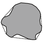
The convexity is a measure relating to surface roughness of a particle. It is calculated by dividing the convex hull perimeter by the actual particle image perimeter. The convex hull perimeter may be explained as the length of an elastic band put around a particle, as shown in figure 2. Values for the convexity range from 0-1. A smooth shape has convexity of 1 while a spiky or irregular object has a convexity closer to 0. Agglomerates generally have rough surfaces, which correspond to a lower convexity values.
|
This article describes, with examples, the use of the above size and shape parameters, either independently or in combination with each other, for the identification of agglomerates. The article also exemplifies how automated image analysis helps reduce the workload associated with agglomerate detection by manual microscopy. Finally, the article discusses the use of imaging in combination with Raman spectroscopy for the detection of multicomponent agglomerates.
Agglomerated particles are generally expected to have a larger particle size than the primary particles present within a sample. However, sometimes a manufacturing process may produce large primary particles. If this is the case, use of the particle size (CED) and circularity data together may provide a means of identifying particles which are agglomerates.
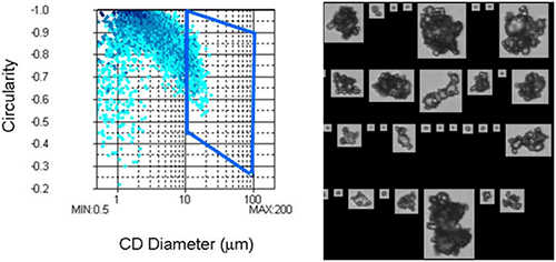
Figure 3a shows an example data set obtained for a sample which was thought to contain agglomerates. The CED is plotted against circularity to produce a scattergram. The depth of color within the scattergram denotes the particle concentration within each region of the plot: this confirms that most of the particles within the sample are small and spherical. However, there is a region of the plot where the particles are large and have low circularity. These particles are likely to be agglomerates formed of smaller particles.
Confirmation of whether agglomerates can be classified by selecting particles with a high CED and low circularity can be obtained by selecting this region of the scattergram and looking at the images of the particles obtained during the measurement (figure 3b). This confirms that these particles are, indeed, agglomerates. So, classification using these parameters provides a reasonable way of detecting agglomerates in this case.
|
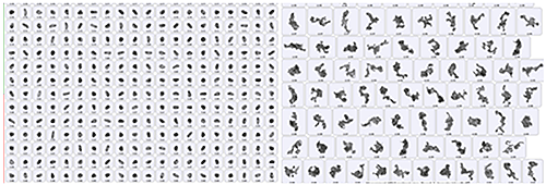
Many samples agglomerate in a way which produces fractal-like agglomerates, where 'strings' of small particles are created. An example of this mode of agglomeration is show in figure 4. Agglomerates like this are often seen within suspension or emulsion samples where the force of adhesion between the particles is relatively small. As a result, any agglomerates which form will have a very open structure.
|
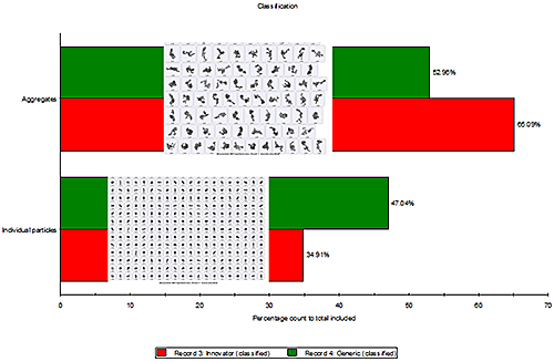
For samples like the one shown in figure 4, identifying particles which have a large size and a low convexity provides one route to identifying and classifying agglomerates. This is effective because the primary particles within the sample are both small (low CED) and have a smooth surface (this is common for emulsions or milled materials). In this case, if agglomerates are classified as those particles with a CED of greater than 5 µm and a convexity of less than 0.993 then a robust classification can be achieved, allowing the degree of agglomeration within different samples to be assessed, as is shown in figure 5. A quick check of the images of the particles obtained within each class confirms that the classification method applied is successful in isolating agglomerates.
|
Sometimes, a sample may contain primary particles which are not spherical. In such cases, classification based on size and a single shape factor may not provide a robust way of detecting agglomerates. Instead, it may be necessary to combine multiple size or shape parameters to classify agglomerates and differentiate them from other particles present in the sample.
A simple example of this is provided by the sample shown in figure 6. This sample is primarily made up of smooth, spherical primary particles that have a small particle size (low CED, high circularity and high convexity). However, it also contains slightly larger particles that have not been processed correctly and are therefore misshapen (higher CED, lower circularity and high convexity). Finally, it contains fractal-like agglomerates (higher CED, lower circularity and lower convexity).

|
In this case, primary particles, misshapen particles and agglomerates were individually detected and classified by using a combination of the circularity and convexity values for each particle. The final classification scheme which was applied is given in table 1. As with the previous examples, confirmation of the success of the classification method was obtained by viewing the images of particles within each class.
| Particle Type | Classification | Example particle |
|---|---|---|
| Primary Particle | Circularity > 0.96 |

|
| Misshapen Primary Particle | Circularity ≥ 0.896 < 0.96 |

|
| Agglomerate | Circularity < 0.896 Convexity < 0.873 |

|
In some cases the primary particles within a sample may occur in a variety of different shapes and sizes, such that it is difficult to differentiate between agglomerates and primary particles on the basis of shape and size alone. In such cases, sorting the particles detected within the sample in order of their particle size may help users to manually identify and classify agglomerates. This method relies on the fact that the human eye can often identify different particle types in situations where mathematical image analysis may fail.
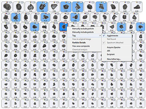
Figure 7 shows an example set of particle images obtained for a sample using the Morphologi G3 automated imaging system. The images are arranged according to the particle CED, such that particles with the largest CED appear at the top of the list and smaller particles appear towards the bottom of the list. Arranging the particle images in this way enables a user to quickly view the particles and identify which are likely to be agglomerates. These can then be manually tagged and classified. In this case, the particles with a blue background in figure 7 were tagged as agglomerates by the user following detailed visual observation of each particle. The Morphologi G3 is capable of returning to the particle of interest on the sample slide, allowing the user to view the particle using different image magnification or light levels and therefore aiding agglomerate identification.
|
Once a user has manually tagged particles as agglomerates, further assessments can be made to identify if there are any particle size or shape parameters which can be used to differentiate primary particles and agglomerates. This would enable future automation of the classification process.
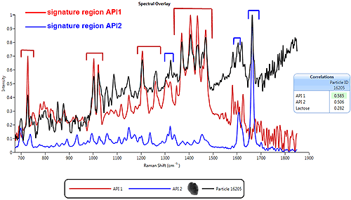
Figure 8 shows the Raman spectrum of a particle (in black) obtained using the Morphologi G3-ID MDRS system, overlaid with the library spectra for two pure components (Active Pharmaceutical Ingredient (API) 1 and API 2) known to be present in the sample. This particular particle was selected for Raman analysis as it had a particle size and shape which suggested that it may be an agglomerate. A comparison of the particle spectrum with the spectra for API1 and API2 shows that it contains features relating to both pure components. This confirms that the particle is a Multi-Component Agglomerate (MCA).
|
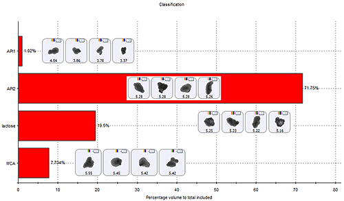
Techniques like MDRS enable a statistically-significant number of particles to be analysed in order to obtain particle size, shape and spectral information. Comparison of the particle spectra with pure component spectra then enables the entire sample to be classified, as shown in figure 9. This includes obtaining a measure of the degree of agglomeration of the sample.
|
The images of the particles show in figure 9 for each particle class confirm the challenge associated with agglomerate identification in this case. The pure components and MCAs have a similar particle size and shape. It is the combination of particle size and shape measurement with Raman spectroscopy which enables the definition of an agglomerate classification scheme.
The identification of agglomerates is seen as a challenge across many different industries. Agglomeration has the capacity to modify the properties of a powder, such as flowability, surface area and dissolution rate, which may ultimately affect a final product's quality. In order to identify agglomerates, a suitable and robust analytical method is required.
Automated image analysis systems provide a means for the classification of agglomerates, by differentiating particles based on their morphological parameters. The inclusion of spectroscopic measurements alongside imaging, in the case of MDRS, allows the identification of the chemical composition of particles, aiding understanding of the type of agglomeration occurring with the sample (cohesion or adhesion). Together, these techniques enable a statistically relevant particle population to be analyzed quickly for effective identification and classification of agglomerates. These techniques can therefore be used to establish robust analytical methods for the analysis of agglomerates, aiding users in ensuring product quality remains consistent.
Maryam Maghsoodi, Katayoun Derakhshandeh and Zahra Yari, "On the mechanism of agglomeration in suspension", Advanced Pharmaceutical Bulletin, 2012, 2(1), 25-30
Gary Nicolas, Stephan Bynard, Mark J. Bolxham, Joanne Botterill, Neil J. Dawson, Andrew Dennis, Valerie, Nigel C. North, John D. Sherwood, "A Review of the Terms Agglomerate and Aggregate with a Recommendation for Nomenclature Used in Powder and Particle Characterization", Journal of Pharmaceutical Sciences, VOL. 91, NO. 10, October 2012